
Blog / Engineering guide
LH vs LW Pressure UF Modules | A Practical Selection Guide
Compare HOSON LH and LW pressure UF modules using feed chemistry, net output, rack fit, cleaning exposure and acceptance evidence.
HOSON WATER editorial · 8 min read
Published · Updated
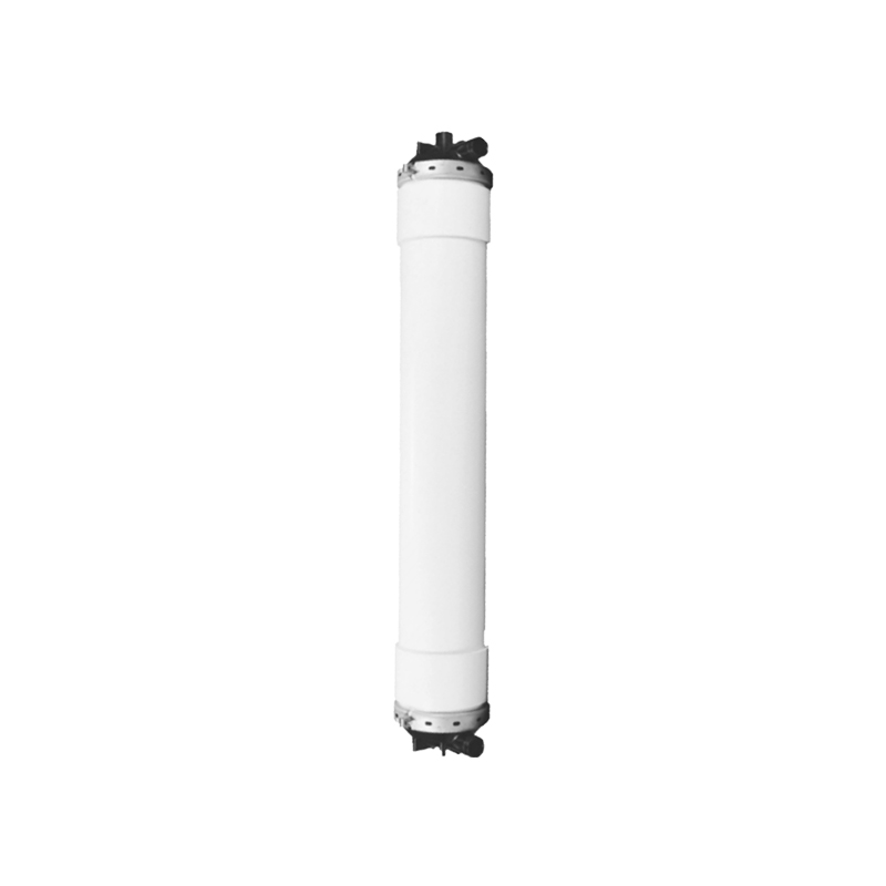
Choose the module around its operating duty
Select an LH or LW pressure UF module by matching the water, required net production, rack connections and approved cleaning exposure. Start with these four items before comparing membrane area or price. A module that fits a manifold still needs a process assessment, while an attractive filtration rating needs a clear statement of the conditions under which it applies.
This guide is for engineers qualifying a new rack and procurement teams considering a replacement. It offers a way to organize the inquiry and review vendor responses. Product facts below refer to HOSON catalog entries checked on 23 November 2026. The sizing calculations are hypothetical engineering examples. The supplier should approve the actual operating envelope, cleaning procedure and installed arrangement for the selected model revision.
Identify the exact family and material variant
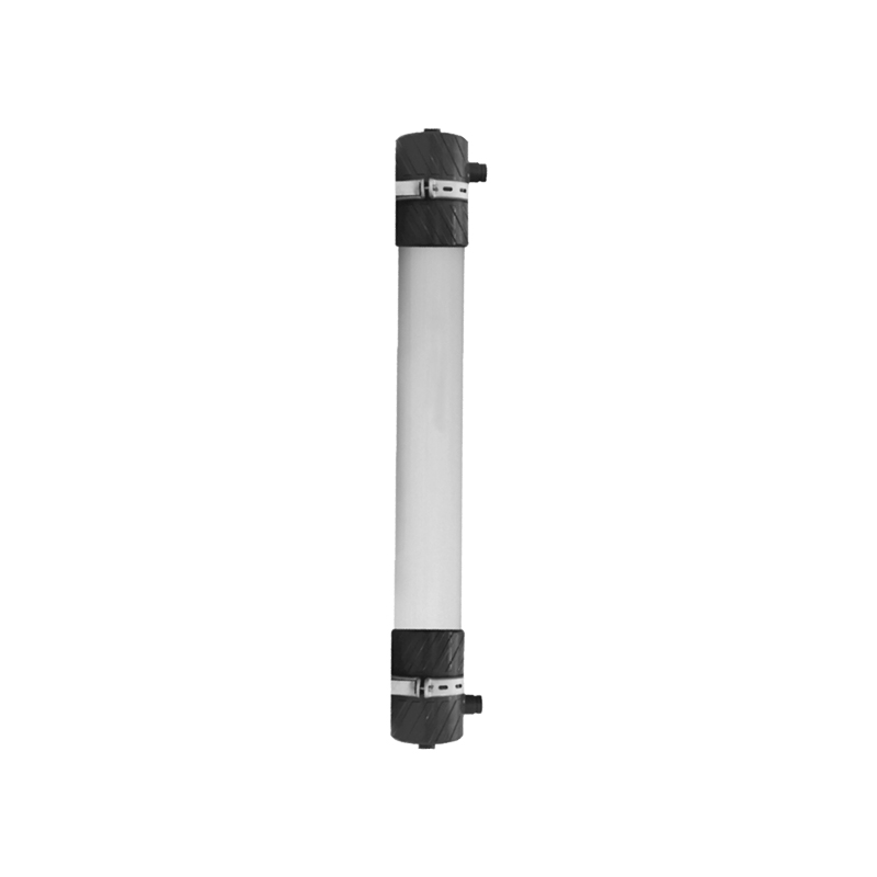
HOSON identifies the LH family as PVC alloy with a nominal pore size of 0.01 µm. Its LW component listing identifies PVDF and PM variants at 0.02 µm. These distinctions help define the shortlist. They do not establish the operating flux, chemical dose or removal credit for an individual installation.
Include the full model code and revision in the purchase specification. Record the material shown on the offered datasheet, the wetted construction and the model suffix. For replacement work, photograph the installed nameplate before asking for a substitute. Keep a copy of the original bill of materials because a changed seal, connector or housing can matter even when the basic membrane family remains the same.
Ask the vendor to explain any difference between a component sheet and an integrated system brochure. Use one approved schedule of operating and cleaning conditions in the final order.
| Selection question | Information to request |
|---|---|
| Membrane identity | Full LH or LW code, material and revision |
| Mechanical interface | Approved dimensions, ports, supports and seals |
| Process duty | Feed basis, net production and operating cycle |
| Chemical exposure | Agent, concentration, time, temperature and cumulative exposure |
Build a feed profile that captures variability
A useful feed profile describes what reaches the module inlet during ordinary and difficult operation. Give the sampling location and explain every upstream treatment step. Record temperature, turbidity, suspended solids and the constituents relevant to the source. For a reuse stream, describe production batches, cleaning discharges and any oil or unusual chemical exposure. For surface water, include known storm or algae periods.
Separate measured results from estimated values. A laboratory report without a date or treatment history can lead to an incorrect assumption about the UF feed. If a clarifier was bypassed when a sample was collected, keep that note with the result. Include the durations of adverse conditions and the action the owner can take when they occur.
This information helps the designer decide whether the shortlist needs additional upstream protection or a pilot. It also defines the conditions that should trigger reassessment after commissioning.
Keep pressure limits separate from useful capacity
The pressure at the module inlet, the pressure across the membrane and the backwash differential describe different loads. Specify where each pressure is measured and the maximum transient the assembly may see. Review the pump curve, valve sequence and pressure protection together. A control setpoint that looks acceptable at steady flow can still produce a short excursion during a rapid valve change.
Ask the supplier to state design filtration flux and the associated temperature and feed basis. Review how that flux changes under adverse conditions. A broad catalog flux range leaves the project engineer to establish the working point. The chosen point should support the required production, cleaning interval and reserve philosophy.
Document the operating mode at each pressure limit. This prevents a backwash allowance from being used as a filtration setting and lets the control team implement the intended protection.
Calculate membrane area from an explicit cycle
Consider a hypothetical rack required to deliver 40 m³/h averaged across a full operating hour. Assume the preliminary design uses a gross filtration flux of 60 L/m²/h, a filtration duty fraction of 0.90 and a product-water retention factor of 0.96 after internal uses. These values are illustrative assumptions and require feed-specific confirmation.
The useful hourly output per square meter is 60 × 0.90 × 0.96 divided by 1,000, or 0.05184 m³/h. Dividing 40 by 0.05184 gives approximately 772 m² of duty area. HOSON lists 40 m² for LH3-1060-V and 56 m² for LW2-0960-F. Pure area arithmetic would suggest at least 20 or 14 modules respectively, before reserve capacity and hydraulic checks.
Those quantities form a preliminary comparison. Ask the designer to validate distribution, backwash, pressure, installation geometry and water quality before treating either as an equipment selection.
Survey connections before approving a replacement
Measure the installed module envelope from fixed reference points. Record port centers, orientation, connection type, available length and the location of supports. Note how much movement the manifold can accommodate without imposing pipe load on the module. A nominal pipe size alone leaves seal dimensions, coupling style and alignment unresolved.
Review feed, product, drain and air connections individually. Trace the valves used during filtration, backwash, draining and cleaning. A replacement must work through every mode the owner expects to retain. Identify any manifold or control change on a marked drawing and include it in the commercial scope.
For a large replacement order, arrange a dimensional review or a trial assembly with the proposed connectors. Record the approved configuration before releasing the full quantity. The review can uncover installation work that a unit-price comparison would otherwise miss.
Review the whole cleaning exposure
Give the supplier a cleaning schedule that names each chemical, concentration, contact time and temperature. Include routine dosing and occasional recovery cleaning. Record whether the module experiences a chemical during filtration, backwash or a dedicated clean. The compatibility review should cover fibers, potting, housing, seals and nearby wetted components.
Where sources show different pH envelopes, obtain a written limit for the exact offered assembly. A pH range is one part of chemical compatibility. Duration, temperature, oxidant strength and accumulated exposure also affect the assessment. Ask how the owner should log exposure and what requires technical approval before the procedure changes.
Check whether the site can prepare, contain and dispose of the proposed cleaning solutions. Include the amount of product water consumed during cleaning in the water balance and the operator time in the operating plan.
Define the quality evidence the project requires
State the filtrate requirements at a named sample point with a measurement method and frequency. If UF supplies RO, coordinate the particulate fouling criteria with the RO designer. If the water enters a drinking-water system, ask the relevant authority what barrier validation and monitoring evidence it requires. Keep those duties visible in the procurement schedule.
A nominal pore size identifies a membrane characteristic. Project acceptance needs a test method, operating conditions and an agreed response to a failed result. Ask the supplier which integrity test the assembled train supports and how it will isolate a suspected module. Confirm how off-spec product is handled while the team investigates.
Plan access to representative samples and preserve the records produced during commissioning. This helps future operators compare the installed train with its original approved condition.
Compare the costs that follow the purchase
Build a common operating worksheet for the shortlisted configurations. Include measured or projected feed-pump energy, air where used, backwash water, cleaning chemicals, labor and waste handling. State the operating hours and delivered-water volume used in the calculation. Keep standby operation and planned cleaning periods visible because they influence useful annual production.
Ask for the proposed spare inventory, storage conditions and replacement procedure. Compare the service time required to remove one module and the quantity of water lost when its train is isolated. A low element price can accompany additional manifold changes or a larger initial spare holding.
Treat predicted service life and savings as assumptions until supported by a comparable basis. A bid comparison becomes easier to audit when it shows the input, unit cost and calculation behind each annual cost item.
Plan receipt, storage and the first installed baseline
Include receipt inspection in the purchase plan. Ask the supplier which packaging, preservation condition and storage period apply to the exact module. Record how the receiver will identify each item and which signs of transport damage require review. Keep serial numbers, packing records and photographs with the delivery inspection. This information helps distinguish a supply discrepancy from an installation issue discovered later.
Confirm when the site's storage clock begins and what maintenance or inspection is required before installation. Review expected ambient conditions and the availability of a suitable protected area. If construction is delayed, ask the supplier to approve any change in preservation or storage method. Record the approval against the affected inventory so all modules receive the same controlled treatment.
Before installing the first module, verify the rack condition and the revised connection drawing. Clean and inspect the relevant pipework under the approved commissioning procedure. Record any change made to accommodate the replacement. Confirm that the control system identifies the correct active area and model-specific operating limits.
Use the first stable operating period to collect the agreed baseline for production, pressure, temperature and quality. Compare it with the accepted configuration and close the inspection record before releasing the remaining modules for routine duty. This sequence gives the owner traceable evidence from delivery to operation and a practical reference for later replacement orders.
Use a qualification matrix to close the order
Create one row for each unresolved interface and assign an owner. Useful rows include feed data, working flux, net output, connection drawing, cleaning limits, integrity method, control changes and delivery inspection. Ask bidders to identify exceptions directly against these rows. Carry the accepted responses into the order and commissioning plan.
For new applications with substantial feed uncertainty, identify a pilot decision before selecting the full rack. Define which observation would change area, pretreatment or cleaning frequency. This keeps the pilot focused on an actual equipment decision.
Send HOSON the feed analysis, required net duty, operating schedule and measured rack drawing. Request a configuration-specific LH or LW proposal with the current datasheet and its exceptions to your matrix. The response should leave the buyer with a clear equipment boundary and a testable duty.